Zillij
Contents
- 01 Quick Start Workflow
- 02 Interface Overview
- 03 Snap System
- 04 Add Shapes [A]
- 05 Select / Move [S]
- 06 Rotate, Orbit & Mirror a Layer
- 07 Connect Points [C]
- 08 Generate Line at Angle
- 09 Cut Lines [X]
- 10 Tile [T] — Radial
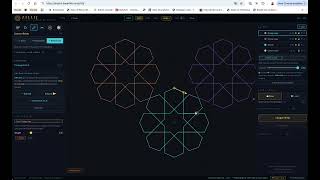
- 11 Tile [T] — Tessellate
- 12 Tile [T] — Mirror Fold
- 13 Finish [B] — Closed Regions
- 14 Finish [B] — Offset Bands
- 15 Layers Panel
- 16 Reference Image
- 17 Save, Load & Export
- 18 Clean Up
- 19 Keyboard Shortcuts & Navigation
01 Quick Start Workflow
Zillij follows a consistent six-stage process. Each stage is a dedicated mode — switch with the icon strip at the top of the left sidebar or with its keyboard shortcut.
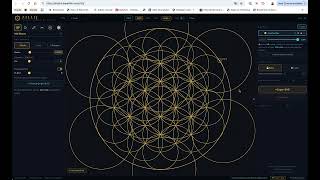
- Add construction geometry — Place a circle at the origin (set Radius first). Add a polygon at the same centre. These form the skeleton from which pattern lines emerge. Keep them in the Construction layer (layer id 0, always present).
- Lock the Construction layer — Click the lock icon next to the Construction layer row so cuts and drags cannot accidentally touch it. Lower its opacity to 15–20% to keep it visible for snapping without cluttering the design view.
- Connect Points — Switch to a new layer. In Connect Points mode, draw design lines between intersection snap points. Enable Symmetry (Propagate to N) for live N-fold mirroring as you draw.
- Apply Tile symmetry — Switch to Tile mode → Radial tab, set N and click Apply to complete the rosette (or use Tessellate / Mirror Fold instead, depending on the composition).
- Cut Lines — Click segments to hide them. Cuts travel with the geometry through undo, redo, and saves.
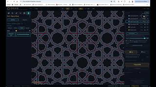
- Finish — Switch to Finish mode. Use Close gaps then Find Closed Regions to build colour-coded tile fills, and/or the Bands tab to generate chiseled or woven divider geometry. Export SVG.
02 Interface Overview
Header Bar
The header has three zones: left (logo, Undo/Redo), centre (view and snap controls, floating over the canvas), right (live cursor coordinates).
| Control | Function |
|---|---|
| ↩ Undo / Redo ↪ | Step backward/forward through history (also ⌘Z / ⌘⇧Z / Ctrl+Y) |
| ⊡ Fit | Zoom to fit all geometry (also F) |
| Grid | Toggle background grid display (on by default) |
| Isect | Toggle intersection point dots (off by default) |
| Fill | Toggle shape fills (off by default) |
| Snap ▾ | Opens the snap dropdown — see §03 |
| Dark / Light | Toggle theme. Construction lines shift between gold (dark) and dark ink (light). Preference is remembered across sessions. |
| ? Help | Opens this reference document in a new tab |
| Coordinates | Live world-space cursor position, far right |
Navigation
- Zoom: scroll wheel — zooms toward the cursor position
- Pan: Alt/Option+left-drag, or middle-mouse drag
- Deselect everything: right-click anywhere on the canvas
- F — fit all geometry to view
03 Snap System
Every click snaps to whichever eligible target is physically nearest the cursor within the snap radius (28 screen px ÷ zoom). The active snap point is shown as a coloured ring, and a label badge near the cursor identifies the snap type.
Snap Toggles (header → Snap ▾)
| Toggle | Default | Snaps to |
|---|---|---|
| Origin | On | World origin (0, 0) |
| Intersections | On | Every shape/connector crossing in G.isects. A crossing is skipped if every edge through it is fully cut. |
| Shape Centers | On | Shape centre points, plus connector/polygon-edge midpoints |
| Grid | Off | Background grid nodes — spacing set by the Grid Size slider (10–200) in the same dropdown |
Regardless of these toggles, a few targets are always considered: connector endpoints, every circle's four cardinal points (N/E/S/W), every arc's start/end points, and any manual Add Points markers.
Add Points (Manual Snap Points)
When placing a circle, the Pts slider adds evenly-spaced snap points around its circumference (default 4). Polygons have their own equivalent, Pts/side, which adds points along each side. Both persist as manual snap targets even after the shape moves.
04 Add Shapes A
Place circles, arcs, and regular polygons that form the construction skeleton. Press A or click the first icon in the mode strip.
Shape Types
○ Circle
- Click anywhere to place at the current Radius
- Click-drag to draw by radius — expands live, release on a snap point to lock the exact radius
- Diameter is echoed below the Radius slider
◡ Arc
- Click 1: set arc centre
- Click 2: set radius & start angle (or enable Compass mode to type/lock a radius instead of dragging)
- Click 3: set end angle — arc closes
- Default direction: short arc (under 180°); Shift+click the end point to force the long arc
- Esc steps back one stage (or cancels, at step 1)
⬡ Polygon
- Set Sides (3–64) — Angle auto-updates to that N's natural orientation
- Adjust Angle (0°–359°) manually to rotate the polygon
- Pts/side (0–12) places evenly-spaced snap points along each side
- Click to place — snaps to cursor
- Each side is placed as an individual connector line — polygon sides can be cut, extended, or deleted independently, exactly like hand-drawn connectors
Radius Control
- Slider range 1–2000 world units; type any value in the number field for precision
- ⊙ Use last segment as Radius appears after measuring a segment in Cut Lines mode — click to apply its length
- ⌥ Option+click a segment in Cut Lines mode captures its length directly and switches you to Add Shapes
Propagate to N
Enable this toggle to reveal an N-fold slider (2–64, default 6). Every shape you place is simultaneously duplicated at N equal rotational positions around the origin — useful for placing all petals of a rosette in one click.
05 Select / Move S
Icon Strip
The Select panel opens with a row of icon buttons above everything else:
| Icon | Action |
|---|---|
| ⊞ Select All | Selects every layer's geometry |
| ✕ Clear | Clears the current selection |
| ⎘ Duplicate | Duplicates the current selection (dimmed until something is selected) |
| 🗑 Delete | Deletes the current selection (dimmed until something is selected) |
| ⤡ Scale | Starts the three-click layer scale flow — see §06 |
| ↻ Rotate | Opens the Rotate & Repeat sub-panel — see §06 |
| ⟺ Mirror | Opens the Mirror / Flip Layer sub-panel — see §06 |
Selection
| Action | Result |
|---|---|
| Click shape | Select single shape |
| Drag empty area | Marquee-select all shapes inside the rectangle |
| Shift+click | Add or remove from the current selection |
| Double-click shape | Select its entire layer (all shapes + connectors, recursively) |
| Delete / Backspace | Delete selected shapes or connectors |
| Right-click / Esc | Deselect everything and cancel any in-progress operation |
Moving
- Drag a selected shape to move it — snaps to intersection points
- Double-click a shape to layer-select, then drag inside the dashed bounding box to move the whole layer. Clicking outside the bbox deselects it.
- The key point (connector endpoint or shape centre) nearest your click becomes the grab point — it snaps to intersection targets during the drag rather than the raw cursor position
- Shift+drag constrains movement to horizontal or vertical, and also nudges a selected layer with the arrow keys (Shift = 10× step)
06 Rotate, Orbit & Mirror a Layer
These live in Select mode, opened from the icon strip (§05). All three act on the currently selected layer, not the whole composition — for whole-canvas radial/tessellate/fold operations, use Tile mode instead (§10–12).
Rotate & Repeat panel
Two tabs:
↻ Rotate
- Set ° (1–180, default 15)
- ↺ CCW / ↻ CW buttons spin the layer in place by that angle
- ↻ Rotate & Align (3-click) — click 1: pivot point on the layer; click 2: the arm point to aim; then move the mouse to rotate live and click a snap target to lock. The layer pivots so the arm lands exactly on the target.
⟳ Orbit
- Copies slider (2–64, default 6)
- Advanced Center X / Y fields, or use the button below to pick visually
- ⟳ Pick Center & Orbit — click the button, then click the canvas to set the orbit centre. N−1 rotated copies are added directly to the source layer.
⤡ Scale
- Click 1: scale centre
- Click 2: arm point (sets reference distance)
- Move the mouse to scale live — ratio = new distance ÷ reference distance. Click a snap point to lock.
Mirror / Flip Layer panel
Flips the selected layer across an axis, in place.
- Quick ⟺ H Flip / ↕ V Flip buttons for an instant 90°/0° flip
- Axis mode: ∠ Origin Angle (slider 0°–180° + preset angles) or ⟵⟶ Two Points (click Pick Axis, then click two points on canvas to define the mirror line)
- Preview axis toggle (on by default) shows the axis line before committing
- ⤢ Flip Layer commits the flip
07 Connect Points C
Draw design lines (connectors) between snap points. These are the visible pattern lines — separate from construction circles and polygons. Press C or click the third mode icon.
Three Sub-Modes
| Sub-mode | Flow |
|---|---|
| ✏ Draw | Click a snap point to set the start, click another to place the line. Click empty canvas (no snap badge showing) to cancel a line in progress. |
| ✂ Align & Trim | Four clicks: click two points to define a line direction (it auto-extends to the geometry bounds in both directions), then click two trim points to keep only the segment between them. Esc cancels. |
| ↖ Select Line | Click any connector to select it and open the Extend Connector panel. |
Through-Line Mode
Enable Through-line mode to auto-extend a drawn line past both anchor points until it meets the outermost geometry crossing in each direction.
- Stored as three independent segments — left extension · anchor-to-anchor · right extension — each cuttable separately in Cut Lines mode
- Fully compatible with Symmetry (Propagate to N) below
Symmetry (Propagate to N)
Enable to draw N copies simultaneously at equal rotational positions. Set N-fold and choose All copies or Every other.
Extend Connector
Select a connector (Select Line sub-mode, or Alt+click from any Connect sub-mode) to open the Extend panel:
- ← Extend / Extend → — grows the line backward/forward to the next intersection (a gold arrowhead marks the end Extend → will grow)
- ↔ Extend Both Ends — extends in both directions at once
- Orange highlights show symmetric partner connectors that will also extend
Line Style
- Colour is inherited from the active layer's colour dot (change it in the Layers panel, not here)
- Weight slider (0.5–8, default 1.5) applies instantly to selected connectors
- Shift+click connectors to multi-select, then adjust Weight to restyle all of them at once
08 Generate Line at Angle
A toggle inside the Connect Points panel. Draws a single connector at a precise angle offset from a reference direction.
- Enable the Generate Line at Angle toggle
- Click P1 — reference start point
- Click P2 — origin of the new line
- Click P3 — endpoint, constrained to the set angle from the P2→P1 direction, snapping to the nearest intersection along that ray. Move the mouse to aim farther out, then click.
- Angle ° slider (−180° to +180°) with presets: 30° 45° 60° 90° 120° 150°
- The mouse side (left/right of the P1→P2 line) determines which way the angle offsets
- The tool disables itself after placing one line — re-enable for the next
09 Cut Lines X
Cuts are non-destructive. Clicking a segment adds its ID to a hidden set — it renders as a faint ghost but is excluded from region detection and Offset Bands. Click again to restore.
Basic Cutting
- Switch to Cut Lines mode (X)
- Hover a segment — it glows red and its length shows in the on-canvas banner
- Click to cut — the segment becomes a faint dashed ghost
- Click the ghost again to restore it
Symmetric Cut
- Enable Propagate to N with an N-fold setting, a Tolerance (1–30, default 8) for matching partner segments, and All / Every-Other pattern
- Hovering a segment highlights all symmetric partners in orange — one click cuts all of them at once
- ✂ Cut All Symmetric Matches button appears once a hovered segment has matches
Circle / Arc Span Cuts
Clicking a circle or arc segment cuts the entire span between its two bounding intersection points, not just one chord — so a full arc section can be cleared in one click.
Measuring Segments
- Hover any segment to see its length live in the on-canvas banner
- ⌥ Option+click a segment to capture its length into the Radius field and switch to Add Shapes
10 Tile T — Radial
Tile is its own top-level mode — press T or click its icon (the 7-hex flower) in the mode strip. It has three tabs: Radial, Tessellate, Mirror. Radial rotates everything on canvas around the origin; Tessellate and Mirror act on a selected layer (or the whole canvas if nothing is selected).
N-fold
Set N-fold (3–64) with the slider or presets (4, 5, 6, 8, 10, 12, 24). A live readout shows degrees per copy and a common name (e.g. "60° per copy · Hexagonal").
Preview and Apply
- ◎ Preview shows the rotated result at fitted zoom without committing
- ⊞ Apply commits — all shapes and connectors are duplicated at 360°/N, 2×360°/N, … around the origin, and intersections are recomputed
11 Tile T — Tessellate
Tiles the selected layer (or the whole canvas, if nothing is selected) across a repeating grid. Build one tile unit, choose a grid type, set the layout, preview, then commit.
Grid Types
| Grid | Description |
|---|---|
| ⬜ Sq | Rectangular rows × columns — set Step X/Y to your boundary size |
| ⬡ Hex | Hexagonal lattice, offset rows — Auto-detect reads a 6-sided boundary polygon |
| ◈ Rh | Oblique rhombus lattice — Angle° (10°–80°) shears the grid; a ◇ Diamond preset button quick-sets 45° |
| △ Tri | Equilateral triangle grid — odd rows are flipped 180° |
Layout Controls
- ⊡ Auto-detect from shape — reads Step X/Y from your geometry's bounds
- Cols / Rows sliders (1–10 each, default 2) — tessellation is a finite Cols × Rows grid, not an infinite repeat
- Step X / Step Y sliders (10–2000)
- Nudge X / Nudge Y — extra offset added each row/column, for interlocking brick-like patterns
- Alt. Row/Col Offset — shifts every other row by a fraction of Step X and/or every other column by a fraction of Step Y (½ = classic brick-wall offset); quick buttons for ½ row, ½ col, ⅓ row, and reset
Cluster Buttons
Shown per grid type — build a small pre-arranged cluster in one click instead of tiling the whole grid:
- ⬡ 7-up Super-Hex (hex grid) — 6 copies around the centre at hex lattice positions
- ⬜ 4-up Super-Square (square grid) — 3 copies in a 2×2 arrangement
- △ 3-up Super-Triangle (triangle grid) — 2 copies, one flipped 180°
Preview and Apply
- ◎ Preview shows the tiled layout at fitted zoom without committing
- ⊞ Apply commits — duplicates all shapes and connectors and recomputes intersections. Cuts inside the tile propagate to every copy.
12 Tile T — Mirror Fold
Auto-generates the reflected half of a composition across a movable fold axis. Select a layer, position the axis, preview, then apply.
Fold Controls
- Fold mode: ⟺ H+V / ↔ H / ↕ V
- Fold X (for H/HV modes) and Fold Y (for V/HV modes) — number field + slider, −2000 to 2000
- ⊡ Auto-detect Fold Axis — reads a likely axis from the selected geometry
- While previewing, arrow keys nudge the fold axis position (Shift = 10× larger step)
- ◎ Preview shows the folded result
- ✓ Apply commits — the reflected copy is added to the composition
13 Finish B — Closed Regions
Finish mode replaces the old always-visible "Closed Regions" sidebar section — press B or click the hexagon icon (last in the mode strip). It has two tabs: Bands (opens first — see §14) and Regions. Region detection finds closed polygon faces in the visible line network and turns them into filled shapes for SVG colour export. Locked layers are excluded.
Workflow
- Close gaps ≤ [n] u — if endpoints are slightly misaligned, set a tolerance and click Run. The status line shows the number of open endpoints and the closest gap distance, so you can judge whether to raise the tolerance or manually connect the gap.
- ⬡ Find Closed Regions — detects all enclosed faces via half-edge face-walking; results appear as coloured fills on the canvas.
- ↻ Regroup → Update Layer — auto-groups regions by side count and similar area (tune with Max groups and Max sides), assigning matching colours to matching tile types.
- Manual assign — click a swatch in the region colour palette, then click any region on canvas to repaint it individually.
Other controls: Show fills toggle (on by default) hides/shows the coloured overlay without discarding the detected regions; ✕ Clear Regions removes them entirely.
14 Finish B — Offset Bands
Generates a new band layer from your visible connectors, circles, and arcs: flanking offset lines on each side of every line, with junction geometry that varies by style. Great for the divider/relief look used in muqarnas panels. This is the default tab when you enter Finish mode.
Style
| Style | Produces |
|---|---|
| Mitered (default) | Full-width bands with mitered junction facets — "chisel spokes" radiating from each junction centre to the band corners — for a beveled, 3-D relief look. No centre ridge line. |
| Woven | Ribbon-style bands (edges only, no ridge/spokes) that alternate over/under at every crossing, with the under strand gapped beneath the over strand. Width is the total strand thickness. |
| Outline | Ribbon-style bands like Woven, but crossings pass straight through — a clean double-line trace of the network with no weave and no bevel decoration. |
| Overlap | Full-width bands like Mitered, plus a centre ridge line down each source connector. At simple 4-way crossings the bands' edges are drawn straight across so the two strands read as flatly overlapping; junctions with 3+ lines still get the mitered spoke treatment. |
Common Controls
- Width slider (1–100, default 15)
- ◎ Preview — computes the band geometry and shows it without committing (button becomes Refresh Preview while a preview is active)
- ◈ Create [Style] Bands — commits the preview as a new layer and hides the source layers it was built from
Woven-Specific Controls
Shown only when Woven is selected:
- Propagate flips to N toggle (default on) + N-fold slider — clicking a crossing in the preview flips its over/under state across all N rotational positions at once
- Weave review — after previewing, click any teal crossing marker to flip which strand goes over. Flipped crossings show a gold marker; a running flip counter is shown. Reset weave clears all manual flips.
15 Layers Panel
Every shape and connector belongs to exactly one layer. The Layers panel (right sidebar, always visible) controls visibility, lock state, opacity, colour, and nesting hierarchy.
Layer Rows
| Element | Function |
|---|---|
| ▼ / ▶ arrow | Expand/collapse nested child layers (only shown if the layer has children) |
| Colour dot | Click to open a colour picker for this layer |
| Name | Click directly into the name to edit it — Enter or click away commits, Esc reverts |
| ⊞ | Select all geometry in this layer |
| 👁 / ○ | Toggle visibility — hidden layers dim to 40% and are excluded from export and region/band detection |
| 🔒 / 🔓 | Toggle lock — locked layers can't be drawn on, cut, or dragged |
| ⧉ | Duplicate the layer |
| ⊖ | Unmerge — restores a merged layer's children to the top level (only shown on rows with children) |
| × | Delete the layer and everything in it (only shown when more than one layer exists) |
Click a row to make it the active drawing layer. Shift+click rows (or use ⊕ Select layers to merge) to multi-select for merging.
Opacity
- The opacity slider shown below the list applies to the currently active layer (0–100%)
- Nested opacity is multiplicative — a child at 80% inside a parent at 50% renders at 40%
- Written to SVG export as a layer-level
opacityattribute
Reordering
Drag any row up or down to restack it — rows lower in the list draw on top.
Merging & Nesting
- With 2+ layers selected: ⊕ Merge N flattens them into one layer (moves all geometry into a single new layer, deletes the emptied ones)
- ⊞ Nest N groups the selected layers under a new parent while keeping each child intact — use this instead of Merge when you want to keep the hierarchy
- ⊕ Merge Visible flattens every currently visible layer in one click, whenever 2+ are visible
- ⊖ Unmerge restores a parent's children back to the top level
16 Reference Image
A collapsible panel in the right sidebar for tracing over a photo or plan. It is not saved in .zillij files — treat it as a session-only tracing aid.
- 📷 Load Reference Image — pick an image file
- Once loaded: filename shown, ✕ removes it, Opacity slider (5–100%, default 50%)
- 👁 Visible / 🔓 Editable toggles — lock it once positioned so it can't be nudged by accident
- On canvas: drag the ⊕ handle to reposition, drag a corner to scale and rotate
- Arrow keys nudge the image when it's selected and unlocked (Shift = 10× step)
17 Save, Load & Export
Save / Load (.zillij)
The native format is a .zillij JSON file capturing everything needed to restore the session exactly.
| What's saved | Detail |
|---|---|
| Shapes | All circles, arcs, and region fills with full properties |
| Connectors | All lines with colour, weight, layer assignment |
| Cuts | Stored as world-space midpoints — survive recomputation |
| Layers | Full hierarchy, names, colours, opacity, lock/visible state, expand/collapse |
| Manual snap points | Add Points placements |
| Tessellation settings | Grid type, step, cols/rows, nudge/offset values |
- Load accepts multiple files at once — each one merges additively into the current canvas as a new top-level import layer, preserving its own hierarchy underneath. There is no destructive "replace scene" load — clear the canvas first (see below) if you want a clean slate.
- Share saves with developer toggle (off by default) — when on, a copy of each save/export is sent to the Zillij developer to help diagnose bugs. Nothing is sent while it's off.
Clear All
The red ✕ Clear All button wipes the entire canvas. It's a normal undoable action, but there's no confirmation step before it fires — save first if the current state matters.
Export SVG
↓ Export SVG opens a sizing dialog before exporting:
- Width / Height (inches) and Margin (inches, applied on each side) — content scales to fill within the margin, aspect preserved
- A live Scale readout updates as you type
- Only visible, uncut geometry is exported; each layer becomes a named
<g>compatible with Rhino, Illustrator, Inkscape; layer opacity and connector stroke/weight are preserved as SVG attributes
18 Clean Up
Collapsed by default in the right sidebar. Runs a single pass over whichever checkboxed operations you leave checked — use after complex tessellations to reduce vertex counts and remove artefacts.
| Checkbox | What it does |
|---|---|
| Duplicate lines | Removes connectors with identical endpoints |
| Short lines | Removes connectors shorter than a minimum length (field, default 2) |
| Isolated connectors | Removes connectors not touching anything else |
| Simplify regions | Ramer–Douglas–Peucker simplification on region polygon vertices (tolerance field, default 1.0) |
| Merge collinear | Groups connectors by infinite line and merges overlapping/touching segments, including chains through junction nodes (gap field, default 2) |
| Orphaned snap pts | Removes Add-Points markers no longer sitting on any circle's circumference |
All are checked by default. Uncheck any you don't want, then click ◈ Run Clean Up — it runs every remaining checked operation in one pass and reports a summary.
19 Keyboard Shortcuts & Navigation
Mode Switching
| Key | Action |
|---|---|
| A | Add Shapes |
| S | Select / Move |
| C | Connect Points |
| X | Cut Lines |
| T | Tile (Radial / Tessellate / Mirror Fold) |
| B | Finish (Regions / Bands) |
| F | Fit view to all geometry |
| ] | Collapse/expand the right sidebar |
| Esc | Cancel the current step of any in-progress tool, or deselect everything if nothing is in progress |
Edit
| Key | Action |
|---|---|
| ⌘Z / Ctrl+Z | Undo |
| ⌘⇧Z / Ctrl+Y | Redo |
| ⌘A / Ctrl+A | Switch to Select mode and select everything |
| Delete / Backspace | Delete selected shapes or connectors |
| Arrow keys | Nudge a selected layer (Select mode), the Mirror Fold preview axis (Tile mode), or the reference image, depending on what's active. Shift = larger step. |
Context-Sensitive
| Key / Action | Context | Result |
|---|---|---|
| ⌥ Option+click segment | Cut Lines mode | Capture segment length → Radius field, switch to Add Shapes |
| ⌥ Option+click connector | Connect mode, any sub-mode | Select the connector (opens the Extend panel) |
| Shift+click shape/connector | Any mode | Add to multi-selection |
| Shift+click arc end | Add Shapes → Arc | Force the long arc (over 180°) |
| Shift+drag | Layer selected, or arrow-nudging | Constrain to horizontal/vertical, or 10× the nudge step |
| Double-click shape | Select mode | Select its entire layer |
| Alt/Option+drag, or middle-drag | Canvas | Pan view |
| Right-click | Canvas | Deselect everything, cancel in-progress operation |
| Scroll wheel | Canvas | Zoom toward cursor |